Monday, September 27, 2010

Fitting mind330

Fitting mind330
mind330 is a mid-range product in the mind™ product family. It contains a number of the features
included in our top-range product mind440, and the fitting bulletins for mind440 apply to mind330
in most cases. However, not all features included in mind440 are available in mind330.

This bulletin outlines the most important differences between the mind330 and mind440 series and
describes the areas where the fitting of mind330 products differs from the fitting of mind440 products.
A few changes which will apply to the entire product range in the mind family with the introduction
of Compass V4.7 are also mentioned. The most important differences between the features included in the mind330 and the mind440 series are summarised in the table below:


Features which differ in the mind440 and mind330 series
Mind 440 Mind 330
15 channels and 15 bands                                   15 channels regulate compression during processing        
The frequency range is divided into 15 bands
10 channels and 10 bands
10 channels regulate compression during
processing                                                         
The frequency range is divided into 10 bands
Speech Enhancer
In the new and improved system, speech
perception in noisy environments is optimised
even further by combining statistical analyses
with information on the client’s individual
hearing loss.
Noise reduction
The Classic noise reduction system continuously
analyses incoming sound statistically
in order to distinguish between speech and
background noise and minimise the effect
of noise.
5 listening programs can be included
5 different programs can be added to the hearing
aid from a selection of listening programs.
4 listening programs can be included
4 different programs can be added to the
hearing aid from a selection of listening
programs.
Zen fractal generator
The Zen program with a choice of relaxing
tones and chimes is available

The Zen/Zen+ programs are not available in
the mind330 series

The practical implications of the different features in mind330 and mind440 for the fitting process are
described in more detail on the next page.

The Fitting section
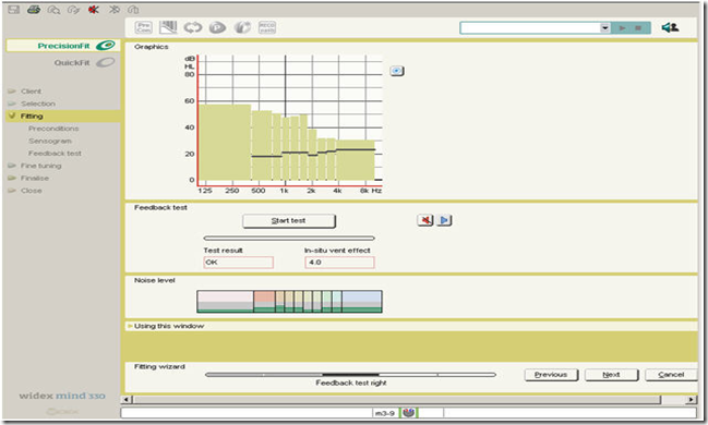
In the mind330 series, signal processing takes place in 10 channels, and the frequency range is divided
into 10 bands during analysis. Accordingly, during the feedback test the maximum available gain is displayed across 10 channels, and the noise level panel shows 10 bars.


image

Maximum available gain is shown across 10 channels. Noise level is displayed across 10 bars.
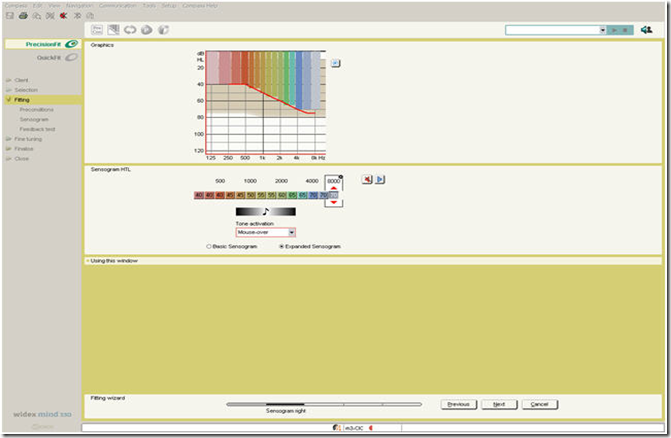
In-situ thresholds are measured in either 4 bands (Basic Sensogram) or up to 14 bands (Expanded
Sensogram). Because Sensogram measuring bands are independent of the hearing aid’s signal
processing channels, even a 10 channel device such as mind330 can utilise the expanded Sensogram
option to obtain detailed information on the hearing loss configuration across frequencies to ensure
the best possible basis for calculating the gain and compression characteristics.

image

The Expanded Sensogram can contain up to 14 bands because Sensogram measuring bands are independent of the signal processing channels.


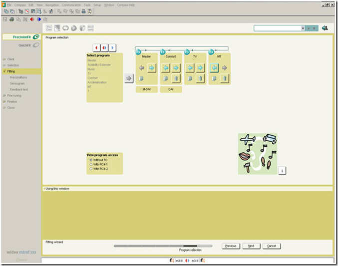
In the Program selection window, four basic listening programs can be enabled for hearing aids in the
mind330 series.


image

mind330 hearing aids can contain four basic listening programs. The Master program is the only obligatory program. The other programs can be added from the list according to the client’s needs and wishes.

The Fine tuning section

Fine tuning the Master program


The four SoundTracker views, which show the real-time performance of the hearing aid in the current
environment from different perspectives, are shown across 10 channels when a mind330 hearing aid
is being fitted. Similarly, the feedback cancelling system is active in 10 channels in the mind330 series.
The default feedback cancelling mode SuperGain is shown in the example below.
The Loudness master handle allows you to adjust gain for all input levels simultaneously, or for the
low, mid or high frequencies separately as in the example below.
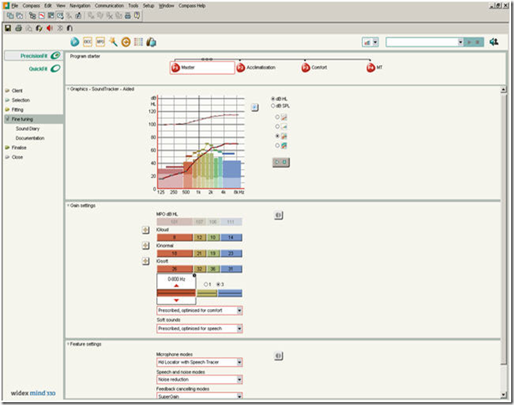
imageSoundTracker view in 10 channels. Separate adjustment of gain in low, mid and high frequencies. The default
feedback cancelling mode is SuperGain.

Fine tuning the Audibility Extender
When fine tuning the Audibility Extender in a mind330 hearing aid, the start frequency is automatically
set to 2,000 or 4,000 Hz on the basis of the configuration of the Sensogram. You can change the
start frequency if necessary by selecting the desired frequency from the drop-down list.
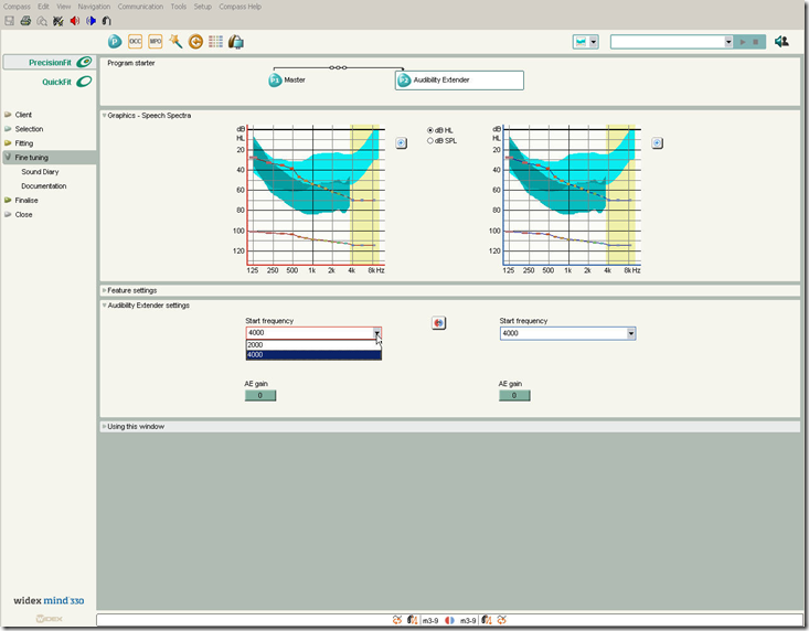
image 8

The MPO manager
With the introduction of Compass V4.7, band-specific adjustment of the Maximum Power Output
settings of the four basic frequency bands becomes possible for mind440 and mind330 products. The
introduction of band-specific output adjustment in the MPO lock means that the maximum output
can be increased or decreased in a specific frequency region without affecting the other regions. A
typical situation where this can be useful is when your client has a highly restricted dynamic range
accompanied by a high intolerance to loud sounds in a particular frequency region owing to, for example,
a steep hearing loss in the high-frequency region.
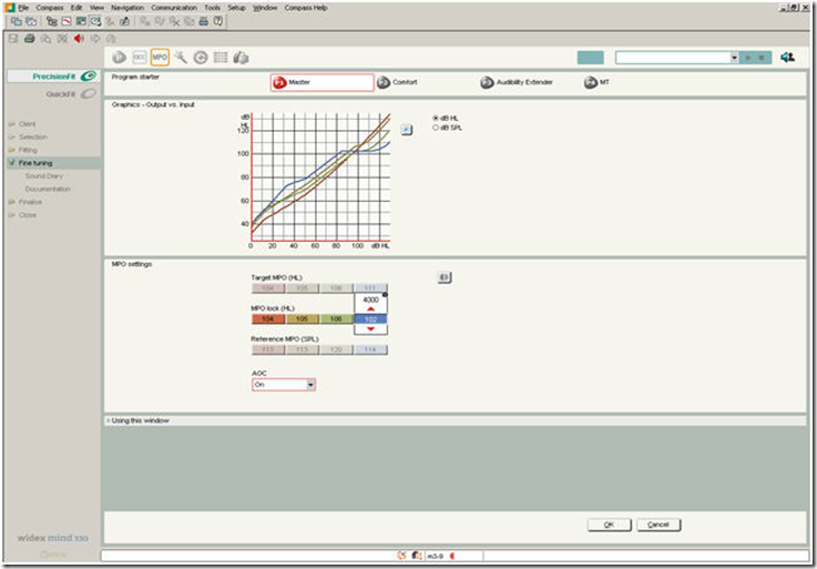
image    Band-specific adjustment of the high-frequency region (2,000-4,000 Hz) using the MPO lock.

The Solution guide
From version 4.7 of Compass, we introduce pictograms in the Solution guide to provide a better
overall view of where changes will apply. Specifically, pictograms are displayed for all those programs
which will be affected by the adjustments when implemented.
If you use the Global solution guide to deal with the general performance of the hearing aid, the Master
program and any additional listening programs which are linked with the Master program will be
affected by your adjustments. Pictograms representing the Master program and the programs which
are linked to it will be displayed to remind you that your changes will affect all the programs unless
you choose to unlink some of them from the Master program.
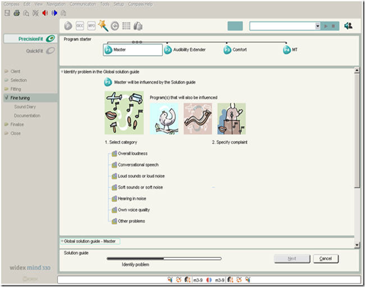
image Pictograms indicating that the Master program, Audibility Extender, Comfort program and MT program will be
influenced by the adjustments made via the Global solution guide.

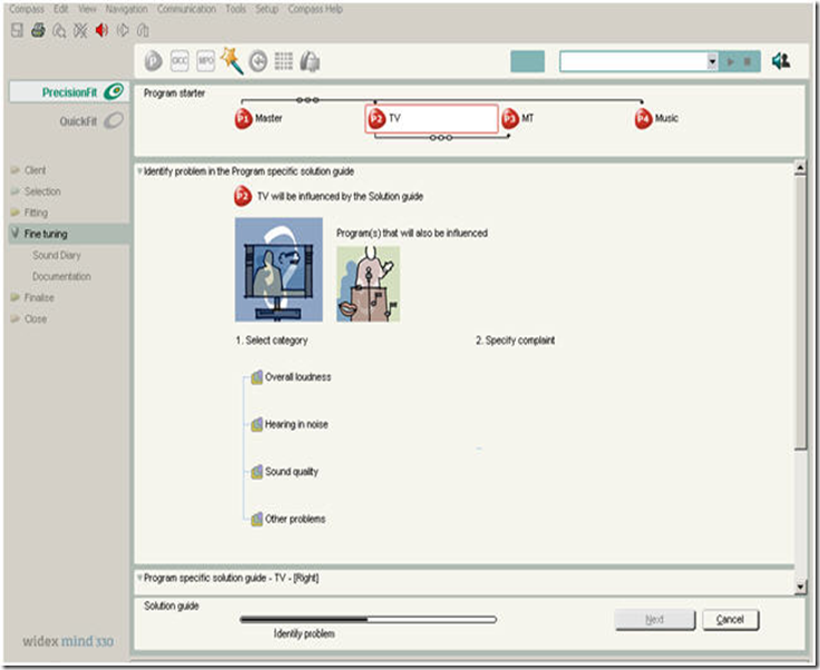
If you use the Program specific solution guide to solve user complaints related to a specific program
other than the Master program, only one pictogram representing that program will typically be displayed
to highlight the fact that the adjustments will apply to that program only. However, the telecoil
program and the microphone and telecoil program may be linked to other programs than the Master
program. In such cases, a pictogram representing the T or the TM program will also be visible to
remind you that your changes will apply to that program also.
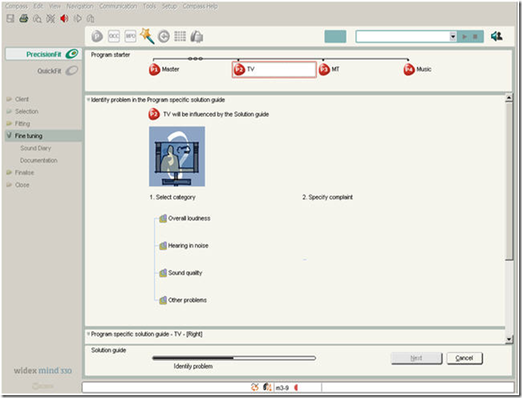
image Typically, a single pictogram is displayed when the Program specific solution guide is used.

image

The T and TM programs may be linked to other programs than the Master program. In the example, the TM program
is linked to the TV program and will be affected by whatever changes are made to the TV program
Friday, September 24, 2010

Widex Ireland Clean & Care Kits for Hearing Instruments

Widex Cleaning & Care Line

Widex Ireland is well aware of the current economic climate and the difficulties that our customers face. We strive to support our customers with our innovative product line and the introduction of campaign offers that truly assist our customers to preserve their margin and increase their market penetration. Widex believes in the complete hearing solution concept, with this in mind we would like to re-introduce our Cleaning & Care line and explain why we think it can truly benefit your business, increase your margin and introduce ancillary revenue flow.

The advantages of supplying a Cleaning & Care kit to your Patient

  • Your customer will have a more hygienic, safe and reliable hearing instrument
  • You increase your own value as a service supplier by providing a complete hearing solution service
  • Your Patients will return to your clinic to purchase refills which will improve your Patient relationship, aid Patient retention and provide you with an added source of ancilliary revenue.

How Widex can assist you

Widex offer  well branded and attractively packaged Cleaning & Care kits for both ITE and BTE hearing instruments, along with refills. The Cleaning & Care kits come complete with everything the Patient needs to take care of their hearing instruments on a daily basis. We think the addition of the line to your offerings will assist you in several ways,

  • Enforces the perception of you as a premium hearing care provider
  • Increases your Patients awareness of the primary causes of instrument breakdown
  • Build your Patient’s trust in you, your care package and your concern for them
  • Creating satisfied customers with decreased breakdowns
  • Increasing and consolidating the relationship with your Patient by repeat visits not associated with problems

The Cleaning & Care refills should over time become a valued noncore additional revenue stream.

The ITE Clean & Care Kit and it’s contents

The BTE Clean & Care Kit and it’s contents

Thursday, September 23, 2010

Fitting m-models with Compass

Audiological Bulletin no. 27


9 502 1036 001 – A 11 07
News from Audiological Research and Communication


This bulletin describes the four main steps in fitting m-models with Compass V4. The descriptions refer to the options in the Selection and Fitting sections in Compass, including change of the acoustic identity of the m-models and the Preconditions, Sensogram, Feedback test and Program manager windows. Please refer to compass in order to see the details of the screen. Remember that Compass offers several help functions to explain the different options in the program: Tooltips, Using this window panels and the help manual. The m models follow the fine tuning procedure of their respective product family. For detailed information about the fine tuning please refer to the specific bulletins for the respective family.

Selection
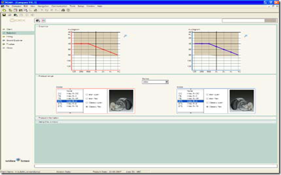
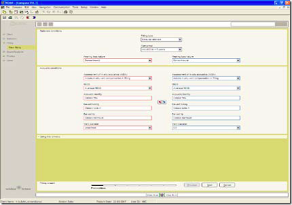
In the Selection section, you can select the acoustic identity of an m-model. For the m-models you have a choice of four different acoustic identities: élan open, élan flex, Classic open and Classic flex. Please observe that each of the models has its own fitting range. After selecting the right model for your client, you go on to the Fitting section by selecting Fitting in the menu in the left side of the window. The easiest way of fitting m-models is by following the Fitting wizard. You could also proceed by connecting the m-model using the connect icon in the Toptool bar.


image

On-line communication
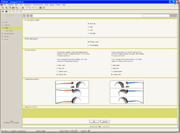
After selecting the appropriate hearing aid model, you must establish contact with the hearing aid. On-line communication is available in binaural, right or left mode. You can also choose simulated mode if no hearing aid is attached via the computer. Based on the client data, Compass will make a choice as default.

Define starting point
The Fitting wizard will automatically guide you through the essential steps of the fitting of m-models. If you prefer to do the fitting without the guidance of the Fitting wizard, you may do so by going to Fitting status.
image

Acoustic identity
You may tailor the acoustic identity of the m-model in the On-line communication window. Use the radio buttons in the acoustic identity section to adjust your choice. You have the choice between élan open, élan flex, Classic open, Classic flex. If you change the acoustic identity, Compass will configure the hearing aid to the new acoustic identity. The configuration can take up to several minutes depending on the programming interface you use. It is very important to make sure that the acoustic identity of the hearing aid is identical to the physical setup of the hearing aid.

The first fitting step - Preconditions
After you have established contact with the hearing aids, you proceed to fitting. Here the first step is to define the fitting preconditions. Most of the parameters in the Preconditions window have been pre-set based on the age and audiogram data stored in NOAH/InfoTrack, but if desired, they can be changed. The choices in the Preconditions window will depend on the selected acoustic identity of the hearing aid.


image

Fitting type
If you have connected two hearing aids, Compass will automatically select the binaural rationale. If only one hearing aid is connected, the monaural rationale will be selected. The latter will result in a slight increase in amplification to compensate for the loss of binaural summation.
Age group
The age group is automatically pre-set based on the age information stored in NOAH or InfoTrack. if an age younger than five years is selected, the paediatric rationale will be used to ensure that the smaller ear canal in young children is taken into account in the fitting. An extra step will be added to the Fitting wizard, allowing you to indicate audiogram transducer information.
Hearing loss nature
The type of hearing loss (Sensorineural or Conductive/Mixed) is automatically selected based on the audiogram information stored in NOAH/InfoTrack. If a conductive/mixed hearing loss is indicated, the rationale will automatically compensate for the conductive component with less compression and more gain.
Assessment of in-situ acoustics
For the nearly all the modern models, you can choose how the assessment of in-situ acoustics (AISA) should affect the fitting. Assessment of in-situ acoustics is not available for the FL-m models. For most m models, you can choose between three different approaches:

Include in-situ vent compensation in fitting uses the results of the AISA estimated vent effect for gain
compensation in the fitting, all reflected and displayed in the performance graphics. The Sensogram is displayed as an AISA Sensogram in the SoundTracker and Speech spectra views (in-situ vent effect is included). The gain and output graphics include the in-situ vent effect and gain compensation, as
well as the effect of the vent-transmitted sound path.

Display assessment results only displays the results of the AISA estimated vent effect. No compensation
is applied in the fitting. The gain and output graphics include the in-situ vent effect and the effect of the vent-transmitted sound path.

Ignore AISA (off) neither displays nor compensates for the vent effect. All performance graphics and gain settings in the hearing aid assume a completely unvented shell/earmould (0 mm).
RECD
The real-ear-to-coupler difference indicates how much the individual ear canal acoustics differ from the acoustics of a standard 2cc coupler. These values are used in the calculation of gain to ensure the right amount of amplification at the eardrum. Since m-models are fitted using in-situ audiometric measurements (the Sensogram), the individual differences in ear canal size are, to a large extent, taken into account. However, if desired, you can choose to include individually measured RECD values in the fitting. If you select this option, two extra steps will be included in the Fitting wizard, allowing you to indicate data from the RECD measurements.
Acoustic identity
If you are working with hearing aids that can be defined with different acoustic identities, this field shows the selection you have made. You cannot change the acoustic identity from the Preconditions window, but you can register the ear-set that your client uses. If you want to change the acoustic identity, you must go back to the Selection window.
Ear-set tubing
This option provides a drop-down list where you can identify the exact tube length that your client is fitted with. This option is available for fittings with the élan tube. You can choose between the different tube lengths from 1-5.
Ear-set tip
This option provides a drop-down list where you can identify the exact ear-tip size that your client is fitted with. This option is available for fittings with the élan tube. You can choose between four different ear-tip sizes and a Custom ear-tip.
Vent diameter
This option provides a drop-down list where you can select the appropriate vent size for a given fitting. An
asterisk (*) next to one of the diameters indicates that this is the vent size recommended by Widex for the
particular hearing loss. The fitting rationale will automatically compensate for the impact of the vent in the
fitting. This ensures that the output of the hearing aid at the eardrum is always the output prescribed by the
fitting rationale. The default setting of the vent size is “Undefined”. Please be aware that the vent size dropdown list will differ significantly depending on the selected ear-tip. Due to large vent length differences
between the Custom ear-tip and the Classic earmould and the impact of the vent length on the in-situ vent
effect, Compass offers two distinct parameter sets for these two types of solutions.

The second fitting step – the Sensogram
The second step in the Fitting wizard is the Sensogram. The Sensogram is an in-situ audiometric measurement in which the user’s hearing thresholds are measured through the hearing aid. Place the cursor in one of the value fields, click once and use the arrows to set the level of the test tone. Press the Tone button to activate the tone. You can also use the arrow keys on your keyboard to set the level and the space bar to activate the test tone. Once the thresholds in the four basic bands (500, 1000, 2000 and 4000 Hz) have been measured, you can also measure one or more of the intermediate bands by choosing the Expanded Sensogram option. If the earmould or shell is fitted with a vent, it can be particularly useful to measure the thresholds below 500 Hz, as this will enhance the precision of the vent effect compensation using the AISA strategy. If you are fitting an In-m you have the option to perform the expanded Sensogram. For AK-m you can measure the extra Sensogram threshold at 250 Hz for more precision in the lower frequency area.


The third fitting step – Enhanced feedback test
The third step in the Fitting wizard is the Enhanced feedback test, which serves to initialise the active
feedback cancelling feature in In-m and AK-m models. This system ensures that more gain (Super- Gain) can be provided for the individual fitting without increasing the risk of feedback. If the available gain (measured gain limit + SuperGain) is sufficient to amplify normal conversational speech as prescribed by the rationale, an “OK” will be displayed in the Test result value field. If not, “***” will be displayed, indicating that the feedback test is not OK, either because the physical fit of the hearing aid/earmould is not acceptable, or because background noise interfered with the measurement. You should not proceed with the fitting until you have an accepted feedback test indicated by “OK”. The enhanced feedback test is also used to estimate the in-situ acoustics of the hearing aid fitting. This is expressed as the in-situ vent effect in the Feedback test window. The in-situ vent effect is shown as the vent size needed in an average ear with an average earmould to give a vent effect similar to the one measured on this individual ear. Once measured, the in-situ vent effect replaces the physical vent size selected in the Preconditions window to ensure an even more precise compensation for the loss of amplification associated with ventilation in and leakage around the earmould.
For FL-m the feedback test differs from In-m and AK-m in the following points. The maximum gain
before feedback is measured and the settings in the Flash feedback system are defined by the feedback
test. If the available gain is sufficient to amplify normal conversational speech as prescribed by the
Flash rationale, an “OK” will be displayed in the Test result value field. If not, “***” will be displayed,
indicating that the feedback test is not OK, either because the physical fit of the hearing aid/earmould
is not acceptable, or because background noise interfered with the measurement. You should not
proceed with the fitting until you have an accepted feedback test indicated by “OK”.

The fourth fitting step – the Program manager
The fourth and last step in the Fitting wizard is the Program manager. Here you are allowed to select
the number and types of programs you wish to enable in the hearing aids. You have now concluded a
successful fitting with the m-model and you can proceed to Sound Explorer to evaluate the fitting.

Wednesday, September 22, 2010

Customising receiver ear-sets for Passion hearing aids and removing the battery drawer to connect programming cables

Audiological bulletin no. 50
Customising receiver ear-sets for Passion hearing aids and
removing the battery drawer to connect programming cables

In this bulletin you can learn how to assemble the Passion EarWare. The receiver ear-sets described in
this bulletin are ear-sets from the Widex EarWare RIC box for Passion hearing aids. This bulletin also
contains instructions on how to correctly remove the Passion battery drawer to connect the programming
cables.

You find the following topics in this bulletin:

Acoustic identities: Instant open, Instant flex or Custom flex (vented) 2
• Fitting the EarWare 3
• EarWare maintenance 14
• How to connect the programming cables to a Passion hearing aid 17
• Tips to correct bad fits 18
The procedure of fitting a Passion RIC ear-set is very similar to fitting the ear-set of an m hearing aid
or a 9-model. An additional step in preparing the receiver ear-set is assembling the EarWire with the
receiver.

Acoustic identities: Instant open, Instant flex or Custom flex (vented)


The Passion hearing aid is flexible and can be configured as an instant open fitting or an instant/custom
flex fitting with a vent. When fitting a Passion RIC hearing aid, make sure that the physical and
acoustic identities are the same. Once you have the physical ear-set of the Passion RIC hearing aid,
you must select the corresponding acoustic identity in Compass. This ensures that the correct data set
is loaded into the hearing aid.
Fitting type                                  Acoustic identity                                    Ear-set tip
Open fitting                                     Wire open                      Instant receiver ear-tip open,small (S) or large (L)

image

Flex fitting with optional vent              Wire flex                         Instant receiver ear-tip flex

(size 8 to 11) or  Custom receiver ear-tip flex

imageimage

Note that you cannot convert a Passion hearing aid to have a closed instead of an open acoustic identity
and vice versa when you fit Passion with the iP5 programmer. When using iP5, make sure that
the Passion has the desired acoustic identity, i.e. wire open or wire flex.

3
Fitting the EarWare

Passion EarWare box

When you fit a Passion RIC hearing aid, you need the EarWare box for Passion. It contains all the
items you need to build a Passion ear-set, that is EarWires in different lengths for the left and for the
right ear, instant receiver ear-tip open and instant receiver ear-tip flex in several sizes, lock rings,
anchors, wax guards, vent tubes, vent blocks, receiver housings, an assembly tool, a measurement tool,
a measurement dummy and an instruction sheet showing how to assemble the ear-set.
EarWires for the right ear are marked with red numbers and EarWires for the left ear are marked
with blue numbers.
Note: Do not use ear-tips from the m or élan EarWare box for Passion hearing aids and vice versa.

Step 1: Finding the appropriate EarWire length
image

Start the fitting process by finding the appropriate length of EarWire. To find the correct EarWire length, you can use the measuring tool in the EarWare RIC box. Place the measurement tool on the client’s ear. The desired receiver ear-tip must be level with the centre of the tragus.The ear in the photo to the left needs a length 2 EarWire.

image

Alternatively you can use the EarWire measurement dummy available in the EarWare RIC box. Place the hearing aid dummy on the client’s
ear. Count the plastic markings from the top down. They correspond to the available EarWire lengths.The ear in the photo will be best fitted with a length 2 EarWire.

4
Step 2: Connecting the receiver to the EarWire and attaching the NanoCare wax guard

imageimage

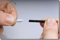
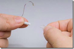
Place the EarWire with the black protector in the black assembly tool. Disconnect the EarWire from the protector and dispose of the protector. Note that the number printed on the terminal end of the EarWire should be facing upwards.

image

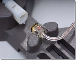
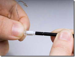
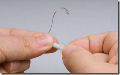
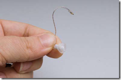
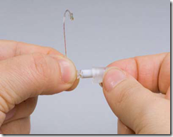
Place the receiver housing with receiver inside in the assembly tool with the side with the number 1 upwards and the small plastic pin downwards. Place the EarWire in the assembly tool with the number pointing upwards. Push the tool together. Remove the EarWire by lifting it upwards and out of the tool.

5
image image

Attach the NanoCare wax guard to the end of the receiver that is not attached to the EarWire. The procedure used is the same as when attaching a wax guard to a Widex ITE or CIC hearing aid. Instant receiver ear-tip open

image

For open fittings select an Instant receiver ear-tip open. This receiver eartip is available in a small (S) and a large (L) version. Select the appropriate size for the client’s ear canal.

Step 3: Attaching the receiver ear-tip: Instant open, Instant flex or Custom flex.
6

image Slide the Instant open ear-tip onto the receiver housing.

image Make sure the ear-tip is securely fastened to the receiver housing. Instant receiver ear-tip flex Select the appropriate receiver ear-tip from the four sizes, from 8 (smallest) to 11 (biggest).

7

image

Push the receiver housing into the larger of the two canals in the Instant
receiver ear-tip flex.

image Make sure the blue or red number on the EarWire and the anchor holes
are still visible. Vent: There are three vent options for the Instant receiver ear-tip flex: 1.7 mm (default), 1.0 mm and closed. 1 mm vent: insert the vent tube in the Instant receiver ear-tip flex. 0 mm vent: insert the vent block in the Instant receiver ear-tip flex.

imageCustom receiver ear-tip flex
For the Custom receiver ear-tip flex place the lock ring onto the receiver
housing. The lock ring makes sure that the receiver ear-tip is sealed acoustically and that the receiver sits properly in the Custom receiver ear-tip flex.

image

8
image Insert the receiver and EarWire backwards onto the Custom receiver
ear-tip.

image

9
image

image

Push the Custom receiver ear-tip over the receiver housing.

image

image Make sure that the Custom receiver eartip is firmly secured by the lock ring.

image

10

Step 4: Trimming the anchor (Instant open and Instant flex) if needed

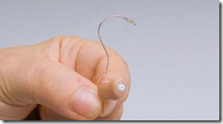
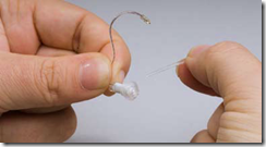
image Thread the pointed end of the anchor through the upper hole.

image

Pull the anchor until it is stopped by
the grip at the end.

image

11
image

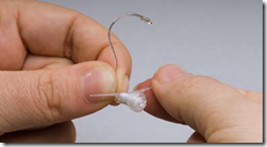
Now bend the anchor downwards until you can guide the pointed end through the lower hole to form a small loop.

image
Define a suitable loop size according to the ear canal of the client.

image

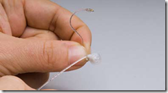
Cut off any excess anchor with finecutting nippers or scissors, leaving only the loop.

image
Take care to cut off all the excess anchor protruding out of the hole, so that the end of the anchor loop is flush with the small hole and there are no sharp edges.

12

Step 5: Connecting the EarWare to the hearing aid

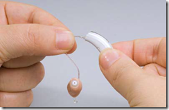
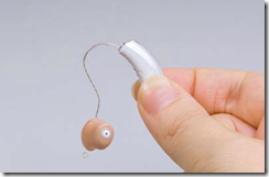
image The EarWire is connected to the hearing aid by means of a click-on mechanism.

image
To disconnect the receiver ear-set  from the hearing aid, pull the ear-set firmly.

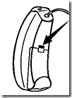
image Insert the colour coding (blue for left, red for right) above the battery compartment of the hearing aid.

image
13

Step 6: Placing the hearing aid on the ear

image
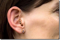
Place the hearing aid behind the client’s ear and place the receiver ear-tip in the ear.

image

The hearing aid should rest comfortably behind the ear without hanging freely above the ear or pulling the hearing aid or the ear-tip. When the hearing aid with the receiver ear-set is positioned correctly on the ear, the EarWire should closely follow the contour of the ear.

14
EarWare maintenance

Exchanging the NanoCare wax guard
Instruct the client thoroughly on how to change the NanoCare wax guard. The receiver can remain in the receiver housing when exchanging the NanoCare wax guard. For Custom receiver ear-tips flex, exchange the NanoCare in the same way as you would with an ITE or CIC hearing aid.

Important
Instruct the client thoroughly that the EarWire may never be washed in water.

Replacing the receiver
If the receiver stops working properly, it should be replaced. See below for instructions on how to replace the receiver for each Passion receiver ear-tip type.

Replacing the receiver housing
To ensure a stable and secure joint, the receiver housing must be changed every time it is removed from the EarWire. The procedure for exchanging the receiver housing depends on the type of receiver ear-tip used.

15

imageInstant receiver flex
1. Push the receiver housing out of the Instant ear-tip by squeezing the solid ear-tip.
2. Place the EarWire and the receiver housing in the closed assembly tool with both the number printed on the receiver housing and the terminal end of the EarWire facing upwards.
3. Hold the EarWire and receiver housing in place while pulling the assembly tool open.
4. Remove the EarWire and the receiver from the tool.
5. Press the receiver and receiver housing into the hole with the pin of the assembly tool. The receiver should eject from the old housing.
6. Place the new receiver housing into the patent hole in the assembly tool, and press the receiver into the new housing.
7. Connect the new receiver housing to the new Ear-Wire using the assembly tool. The number on the receiver housing and the terminal end of the Ear-Wire must point upwards.
8. Attach a NanoCare wax guard.
9. Connect the Instant receiver ear-tip flex.

image Instant receiver open
1. Disconnect the ear-tip from the rest of the ear-set by pushing it off.
2. Place the EarWire and receiver in the closed assembly tool.
3. Hold the EarWire and receiver in place while pulling the assembly tool open.
4. Remove the EarWire and receiver from the tool.
5. Press the receiver and receiver housing into the hole with the pin of the assembly tool. The receiver should eject from the old housing.
6. Place the new receiver housing into the patent hole in the assembly tool, and press the receiver into the new housing.
7. Connect the new receiver housing to the new EarWire using the assembly tool. The number on the receiver housing and the terminal end of the EarWire must point upwards.
8. Attach a NanoCare wax guard.
9. Connect the Instant receiver ear-tip open.

16

image Custom receiver flex
1. Disconnect the EarWire from the BTE part/housing by pulling it off the hearing aid
2. Push the receiver and EarWire using the NanoCare holding pin into the custom flex.
3. Remove and discard the lock ring.
4. Place the EarWire and receiver in the closed assembly tool.
5. Hold the EarWire and receiver in place while pulling the assembly tool open.
6. Remove the EarWire and receiver from the tool.
7. Press the receiver and receiver housing into the hole with the pin of the assembly tool. The receiver should eject from the old housing.
8. Place the new receiver housing into the patent hole in the assembly tool, and press the receiver
into the new housing.
9. Connect the new receiver housing to the new EarWire using the assembly tool. The number on the receiver housing and the terminal end of the EarWire must point upwards.
10. Attach a NanoCare wax guard.
11. Place a lock ring on the new receiver.
12. Thread the EarWire through the Custom receiver ear-tip as described in step 3 of Fitting the EarWare.

Sound bore and vent in the Instant receiver ear-tip flex
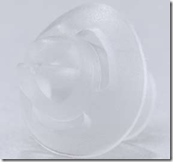
image The Instant receiver ear-tip flex has two canals: The sound bore for the receiver housing (lower canal) and the vent canal (upper canal). You can block the smaller canal partially or completely.
1 mm vent: insert the vent tube (1.7 mm > 1.0 mm)
0 mm vent: insert the vent block

17
How to connect the programming cables to a Passion hearing aid
The Widex CIC programming cables are used to program Passion. Before you can connect these, you must remove the battery drawer. In order not to damage the tiny hinges of the Passion hearing aid we recommend that you follow the procedure below to remove the battery drawer.
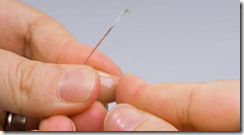
image Open the battery drawer at an angle of 90 degrees. Insert the loose anchor between the hinges. See the pictures to the left.

image Keep the anchor in place and push the battery drawer as if to close it.

image Remove the battery drawer. The Passion hearing aid is now ready to be connected to the Widex programming cables. Use the same cables as for the CIC hearing aids.

image Click them on at an angle of approx. 30 degrees.
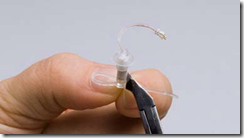
image When you have finished programming the Passion hearing aid, remove the programming
cables.

Attach the battery drawer to the hearing aid as shown in the picture to the left.

image Push it firmly into the hinges. Open the battery drawer and insert a battery (size 10), then close the battery drawer.

18

Tips to correct bad fits
Symptom                                         Cause                                                   Possible remedy
Hearing aid hanging                         EarWire too long                       Choose a smaller length of EarWire. above the ear
EarWire pulling at the
                       EarWire too short                      Choose a larger length of EarWire.
ear and hearing aid 
EarWire protruding from                     EarWire too long                  Choose a shorter length of EarWire     the ear canal                           Anchor loop too large                      Make the anchor loop shorter                                                  Anchor not placed appropriately      Make the anchor loop larger and                                                                                                  position the anchor outside of the ear                                                                                                 canal

Discomfort or itching                 Anchor not trimmed appropriately   Check that the anchor is trimmed

flush with the small hole of the EarWire

Ear-set too small                          Choose a larger length of EarWire

Ear-tip incorrectly sized                 Choose a different size of ear-tip
                                               Anchor size or position            Make the loop smaller and position the 
                                               inappropriate                         anchor inside the ear canal

Ear-tip detaches from the         Ear-tip not firmly pressed         Check that the ear-tip is firmly attached  
ear-set                                    onto ear-set                          to the ear-set

Ear-tip size is too large and so not     Choose a smaller ear-tip                                            easily removed from ear canal

Hearing aid easily detaches    Ear-set has been attached and            Replace the ear-set
from the ear-set                  removed too many times 
                                          Ear-set is being inappropriately          Counsel the client on appropriate   
                                          removed                                        removal technique

Hearing aid falling off the     Anchor not providing adequate     Make the anchor loop larger and position 
client’s ear                         retention                                   it outside the ear canal, or make it 
                                                                                      smaller and position it in the ear canal. 
                                        Ear-tip too small                        Choose a larger size of ear-tip      
                                        Incorrect size of ear-set             Choose another ear-set
 
No sound coming from the     Ear canal blocked by wax             Arrange for or perform wax removal      
hearing aid                                                                     and clean or replace the receiver ear-tip


Download link for pdf copy of the bulletin Customising earsets for Passion